| Public Network | Configuration Information |
|---|---|
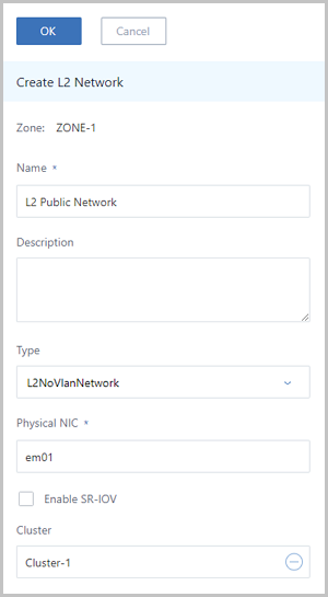
| NIC | em01 |
| VLAN ID | No VLAN |
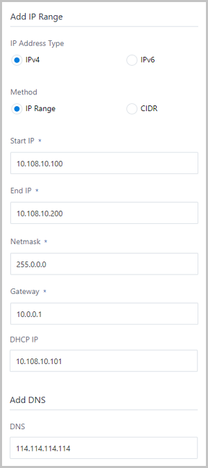
| IP range | 10.108.10.100~10.108.10.200 |
| Netmask | 255.0.0.0 |
| Gateway | 10.0.0.1 |
| DHCP IP | 10.108.10.101 |
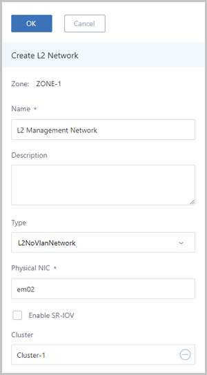
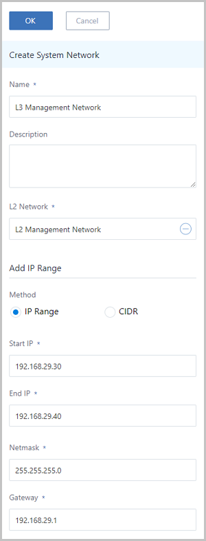
| Management Network | Configuration Information |
|---|---|
| NIC | em02 |
| VLAN ID | No VLAN |
| IP range | 192.168.29.10~192.168.29.20 |
| Netmask | 255.255.255.0 |
| Gateway | 192.168.29.1 |
 Note:
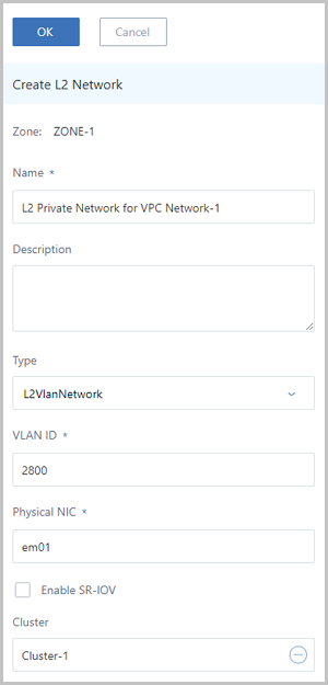
Note: | Private Network | Configuration Information |
|---|---|
| NIC | em01 |
| VLAN ID | 2800 |
| IP CIDR | 192.168.10.0/24 |
| Gateway | 192.168.10.1 |
| DHCP IP | 192.168.10.2 |
| Private Network | Configuration Information |
|---|---|
| NIC | em01 |
| VLAN ID | 2900 |
| IP CIDR | 192.168.11.0/24 |
| Gateway | 192.168.11.1 |
| DHCP IP | 192.168.11.2 |
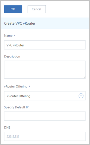
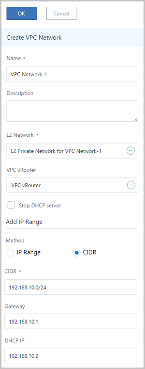
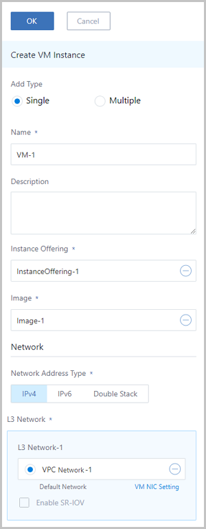
To create a VPC in the Cloud, follow these steps:
 Note: Note: ZStack supports both IPv4 and IPv6. You can choose to add an IP range or a CIDR. This tutorial takes the IPv4 IP address and IP range method as examples.Note:
 Note: Note:
  Note: If the L3 public network in the vRouter offering has an IP range with the IPv6 type, when you create a VPC vRouter, you must use the vRouter image of version 3.10.0 and later.
 Note: Note: The IP ranges cannot be overlapped.Note:
 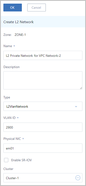 Note: Note: The IP ranges cannot be overlapped.Note:
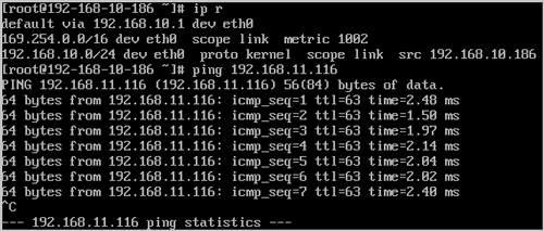
Single.So far, we introduced the basic deployment of a VPC.
© 2023, Shanghai Yunzhou Information and Technology Ltd (云轴科技). All Rights Reserved.
Back to Top
Email Us
contact@zstack.ioEmail Us
contact@zstack.ioEmail Us
contact@zstack.ioThe download link is sent to your email address.
If you don't see it, check your spam folder, subscription folder, or AD folder. After receiving the email, click the URL to download the documentation.Thank you for using ZStack products and services.
Submit successfully.
We'll connect soon.Thank you for using ZStack products and services.